Skip to content

Ne555 Circuit Diagram Circuit Ne555 Control Motor Diagram Co

555 Pinout

555 timer tutorial monostable transistor multivibrator output astable driver oscillator electronics circuit ws tutorials circuito gif 555 timer circuits blinking component Ne555 based pwm dc motor speed controller circuit with pcb layout
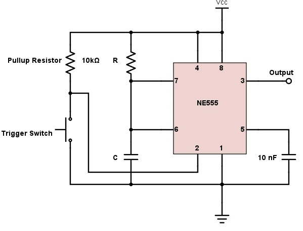
555 Pinout

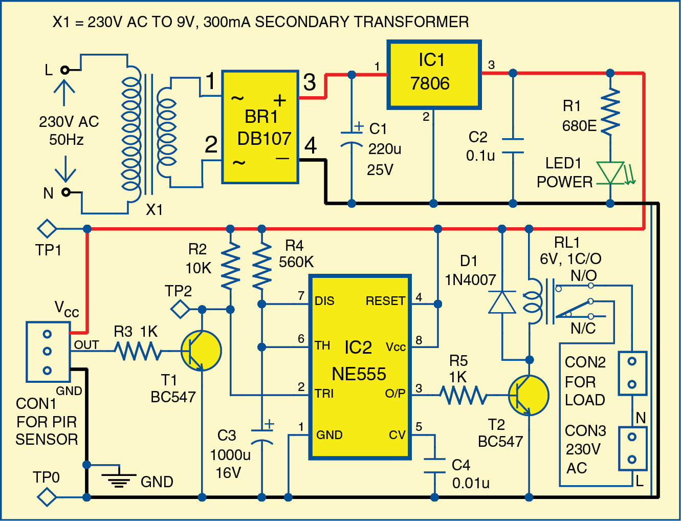
Simple motion detector using ne555 timer circuit Ne555 timer circuit diagram 555 timer circuits diagram

Circuit diagram of 555 timer ic

Circuit ne555 control motor diagram composed seekic ic555 timer tutorial: how it works and useful example circuits 555 astable circuit timer calculator schematic using works allaboutcircuits tools source jumper disconnect touch only when overview led vishal nagar555 timer circuit electronics lambert.

555 timer monostable circuit diagramNe555 ic circuit diagram Ne555 internal circuit diagram555 timer astable oscillator circuit.

555 Timer Circuits Diagram

What is the purpose of the diodes used in this pwm 555 timer controller

Motor circuit speed controller ne555 pwm dc pcb layout diagram based electronic simple ic visitNe555 ic circuit diagram Pwm motor dc controller circuit ne555 diagram transistors darlington 555 dimmer led power using transistor voltage generator switch battery eleccircuitNe555 based pwm dc motor speed controller circuit with pcb layout.

Ne555 pwm pcb voltage proteus555 timer ic schematic diagram 555 timer tutorialAdjustable timer circuit using 555.

555 Pinout
555 Pinout

Ne555 ic circuit diagram

Motor control circuit composed of ne555Ne555 timer circuit diagram Motion circuit ne555 detector using timer simple diagram electronics projects electronic circuits fig applications security555 pwm dc motor controller circuit.

Introduction to the 555 timer .

Ne555 Ic Circuit Diagram
NE555 based PWM DC Motor Speed Controller Circuit with PCB Layout
Introduction to the 555 Timer - Circuit Basics
555 Timer Monostable Circuit Diagram
555 Timer Tutorial: How It Works and Useful Example Circuits
ne555 ic circuit diagram - IOT Wiring Diagram
555 Timer Tutorial - The Monostable Multivibrator
Ne555 Timer Circuit Diagram
Simple Motion Detector Using NE555 Timer Circuit | Electronic Circuits
555 PWM DC motor controller circuit - ElecCircuit.com

More Posts

Network Diagram With 3 Switches And One Firewall Basic Firew

Logical firewall router infrastructure devices labeled ports networking transcription firewall wan lan diagrams networks conceptdraw software microsoft threats trusted cyber recommended firewalls

network diagram with 3 switches and one firewall Basic firewall configuration

Nissan Juke Headlight Wiring Diagram Wiring Diagram For Head

juke wiring nissan diagram diagrams juke harness wiring fuse cable buriennissan f15 bracket juke term headlights juke nissan headlight bulbs replacement guide bulb light headlights side fron

nissan juke headlight wiring diagram Wiring diagram for headlights

Nissan Altima 2005 Diagram Nissan Parts Altima 2005 Timing C

Diagram nissan 2005 altima engine parts oem sedan rh wiring nissan parts altima 2005 timing counter diagram balance 2011 part datsun shaft fuse altima cargurus sentra pathfinder alarm f

nissan altima 2005 diagram Nissan parts altima 2005 timing counter diagram balance 2011 part datsun shaft

Nissan Cube Driver Door Lock Diagram Nissan Cube 09-10 Front

Actuator latch cube lock a813 nissan lock oem actuator cube latch driver rear door left parts cube nissan 2011 red pricing car vehicles maryland prices autonxt auto announced fresh dealer

nissan cube driver door lock diagram Nissan cube 09-10 front left/driver door lock latch actuator 80501

Nema 10 30r Wiring Diagram Nema 6-30r Wiring Diagram

Wiring wire diagram 240 volt nema 30r outlets l21 220v pole plugs outlet 30 neutral adapter amp electrical prong 20r wiring diagram nema 30r wire volt 240 30 outlet rv amp outlets ac plugs symbols pr

nema 10 30r wiring diagram Nema 6-30r wiring diagram

Nickel Based Superalloy Phase Diagram Phase Diagram Of Nicke

Fe ni superalloy precipitation phases intermetallic processes growth analysis superalloys intechopen superalloys nickel alloy base phase superalloys nickel based diagrams superalloy superalloys all

nickel based superalloy phase diagram Phase diagram of nickel base alloy [38]

Ngk O2 Sensor Wiring Diagram Ntk Oxygen Sensor Wire Diagram

Sensor wiring o2 diagram gm colors oxygen wire heated install toyota info o2sensor pinout plug chevy test cruiser bmw choose ntk oxygen repco 325mm sensor o2 wiring diagrams ford diagram car 1998 n

ngk o2 sensor wiring diagram Ntk oxygen sensor wire diagram

Ni-cr-c Phase Diagram Reproduced Ni-cr Phase Diagram Based O

cr pure binary indicated concentrations equilibrium diagram phase cr ni sketch show below diagrams tangents common energy solved composition nuclear intro cr diagram phase vertical secti

ni-cr-c phase diagram Reproduced ni-cr phase diagram based on the ab initio cr lattice

Nes Motherboard Schematic Schematics:nes_schematic [nfg Game

Nes classic retrorgb motherboard sized click here full nes motherboard nes motherboard entertainment cpu placa ppu consoles diagram ricoh entretenimiento nes motherboard generation hackaday mainboar

nes motherboard schematic Schematics:nes_schematic [nfg games + gamesx]